
What Are You Looking For?

Solar mounting systems accommodate uneven terrain through specialized designs such as extended posts, adjustable brackets, and terrain-following structures. These features let you build on slopes and dips without costly grading. An adjustable solar ground mounting system, for example, levels each row while its posts follow the ground below. Finding the right uneven terrain solar mounting solution starts with your site conditions. You can match each slope, hillside, or rocky patch to a system design, a foundation type, and a site strategy that fit. That mapping turns a difficult site into a buildable one, and it keeps structural stability intact over time.
Adjustable mounting systems level each row while posts follow the ground, so you can build on slopes without costly grading.
Match your foundation to the soil: ground screws work well on rocky, uneven ground, and ballasted mounts need no drilling.
Avoid mass grading to save money and protect the environment; let the mounting system follow the natural landscape.
Survey your site first to map slope, soil, and drainage; then choose a system that fits your specific conditions.
Plan row spacing and bracing carefully to prevent shading and keep the structure stable on hillsides.
Terrain falls into four broad categories: gentle slopes, moderate hillsides, steep grades, and irregular rocky ground. Each one changes how you plan a build. Most fixed-tilt ground-mount solar arrays handle slopes up to about 10 degrees with standard posts and rails. Steeper sites need adaptive approaches, and that is where terrain-adaptive systems earn their place.
On gentle slopes, standard posts work well. You extend post length slightly so each row stays level while the feet follow the ground. Moderate hillsides demand more thought. A topographic and slope survey lets you divide the site into slope-based sections. Slope direction then guides module orientation, row layout, and foundation spacing. Steeper zones need different foundation spacing than flat zones.
Connection design holds everything together. Bolts, clamps, and adjustable components must keep their strength after adjustment. You define the adjustment range during engineering, then verify tightness and alignment afterward. This discipline lets a solar mounting system on uneven terrain carry loads safely across changes in elevation. An adjustable solar ground mounting system makes this easier because each support point can compensate for height differences without extra grading.
Steep grades and irregular rocky ground test every part of the design. Elevation differences between posts cause height and tilt variation, so you need defined tolerances for foundation position, post height, rail alignment, and module attachment. Small survey errors accumulate along long rows on a hillside solar mounting system. Careful foundation layout prevents that drift.
Soil conditions matter just as much. Variable soil across a slope affects driven pile, ground screw, or concrete capacity. Geotechnical data on strength, groundwater, and rock depth must feed the foundation design. Drainage also deserves attention. Concentrated runoff can erode soil around foundations, so preserve natural drainage paths and add erosion controls where needed. A complete site assessment for uneven terrain solar mounting covers elevation, slope, soil, drainage, and access. That assessment keeps an uneven ground solar mounting structure stable through every season.
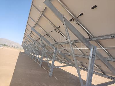
Three design challenges dominate any sloped project. The first is height difference between posts. Each support point sits at a different elevation, so you must define how much variation the structure can absorb. The second is load distribution across rows. Wind and snow loads shift as rows step up or down a slope, and one row may carry more stress than its neighbor. The third is foundation complexity. Depth, bearing capacity, and rock content change from point to point, so a single foundation detail rarely covers the whole site.
You solve height differences with adjustable mounting structures. Extendable posts and slotted brackets let each row reach level without cutting into the hill. The adjustment range becomes a design input, not an afterthought. Load distribution then follows. You model each row as its own load case, because a row near the crest sees different wind exposure than one in a hollow. Bracing ties rows together and spreads force into the foundations. This approach keeps a ground-mounted solar array stable across changes in elevation.
Four system families cover most uneven sites, and each fits a different condition.
|
System Type |
Best Fit |
Trade-off |
|---|---|---|
|
Fixed tilt adaptive |
Gentle to moderate slopes |
Limited adjustment range |
|
Stepped (terraced) |
Moderate slopes up to about 20 degrees |
More site preparation and earthmoving |
|
Flexible adjustable |
Irregular ground with varied post heights |
More components to align |
|
Tensile (cable and anchor) |
Difficult, remote, or rocky terrain |
Needs anchor design and tension control |
Stepped systems create distinct horizontal levels across the slope, much like agricultural terracing. Uniform row heights yield consistent power generation across the array, and the layout provides uniform row alignment on moderate hillsides in the 10 to 20 degree range. The trade-off is real: stepped designs need more site preparation and earthmoving than terrain-adaptive designs. Slopes beyond 10 degrees typically call for stepped or terrain-adaptive systems rather than standard flat-ground designs.
A 21.47 MWp ground-mounted project on mountainous terrain in Malaysia shows the approach in practice. Facing slopes up to 20 degrees, hard soil, subsurface gravel, and stepped slope surfaces, the project combined helical pile foundations, adjustable mounting design, and differentiated vertical 2P/1P layouts. The mounting solution integrated with on-site conditions, which shows stepped approaches work on moderate slopes when foundations and layout engineering are tailored to the site.
Flexible adjustable systems suit irregular ground where post heights vary widely. Tensile systems use tensioned cables and anchors to span difficult terrain with fewer ground penetrations. A terrain-adaptive solar mounting solution often blends these families, following the contour of the land rather than fighting it. Choose the family that matches your slope range, soil profile, and access, then refine the details through engineering.
You match the foundation to the ground, not the other way around. Ground screws and driven piles suit variable-depth anchoring on uneven, hilly sites. Concrete works well on stable bearing soils. Ballasted ground mounts sit on the surface with no drilling at all. Hybrid options combine two of these where one type cannot cover the whole site. Each choice carries its own cost and installation implications on sloped or irregular terrain.
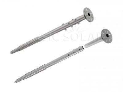
Ground screws and driven piles adapt to changes in elevation because each anchor reaches its own depth. That flexibility makes them a common pick for a hillside solar mounting system. Driven piles bring challenges on rocky ground, though. Exact pile depth and correct positioning become difficult on irregular ground, which slows installation and risks downtime. The machine also needs firm support, and operators should keep the maximum slope at 2° or lay steel plates and sleepers when necessary. On rocky sites, driven posts often hit refusal when they strike an obstruction. Refusal can damage the post, weaken the foundation, and trigger costly remediation such as pre-drilling or abandoning the location.
Ground screws avoid much of that impact hammering. They thread into the soil with less noise and vibration, and they tolerate variable depth well. Treat ground preparation as part of the pile driving process, not a preliminary step. Good preparation improves accuracy and protects equipment during foundation installation on slopes.
Concrete footings adapt to sloped ground because you form and pour each one individually. Each footing gives you a level base plate at any grade. Size the footing plan area from the factored axial load divided by the net allowable bearing pressure. Check overturning next: keep eccentricity at or below one-sixth of the footing width for a no-tension condition. Check uplift and lateral resistance as well, and extend depth below frost line plus 200 mm. In deep-frost regions, that rule alone can push depth to 2.0–2.6 m. Concrete suits stable bearing soils, and it costs more where excavation on rock is slow.
Ballasted mounts need no drilling, so they avoid penetration problems entirely. They stabilize through weight, adding roughly 30–100 kg per m² and keeping tilt low, typically 5–15°, because steeper angles demand far more ballast. The surface must carry the panels plus ballast, and drainage affects slope stability and ground movement. On weak or uneven ground, ballast alone struggles in extreme wind without extra weight or windbreaks. Weigh these trade-offs when you plan foundation solutions for hillside solar projects.
Good uneven terrain solar mounting requirements start with the structure itself. You size every part for the ground it sits on. That means longer posts, stronger bracing, and rails that flex with the land. It also means you plan the site layout before you order a single component. The goal is simple: follow the hill, do not flatten it.
Post length is your first lever. You extend each post so the rail line stays level while the base follows the ground. Custom brackets then connect post tops to rails at the exact angle each row needs. Adjustable mounting structures make this practical, because you set the height at the job site instead of ordering fixed lengths for every position.
Bracing carries the extra load that slopes create. Gravity pulls harder on a tilted array, and wind hits uneven rows at different angles. The right bracing technique depends on your site conditions.
|
Bracing Technique |
Purpose / Condition Addressed |
|---|---|
|
Inclined foundations + reinforced bracing |
Stabilize systems on steep slopes (up to 45°) against gravitational and lateral loads |
|
Diagonal bracing |
Reinforce structures in high-wind and seismic zones (wind speeds up to 70 m/s) |
|
Flexible joints |
Absorb movement and withstand wind/seismic activity in high-wind and seismic zones |
|
Aerodynamic profiles |
Reduce wind loading in high-wind and seismic zones |
Rail flexibility matters just as much. A rigid rail fights every change in elevation. A flexible rail bends to the contour and keeps modules aligned. On very hilly sites, you can also break the array into smaller rows or single-bay tables. Short tables adapt to grade changes more easily than long ones. This mounting structure design for sloped sites keeps stress low and installation simple.
Site work decides how much you disturb the land. Minimal grading preserves the land, can streamline permitting, and makes post-construction restoration easier. Mass grading does the opposite. It causes habitat loss for wildlife and native plants, disrupts natural drainage, and produces soil erosion and dust. Avoiding this disruption lets stakeholders uphold clean energy's environmental promise.
Grading reshapes terrain through leveling or cut-and-fill. That work adds risk, cost, and environmental impact. Modern trackers, racking, and installation methods let projects follow the natural landscape instead of forcing the land to fit the site. New alternatives can reduce or essentially eliminate the costs and impacts of grading even on difficult topographies. That opens productive, cost-effective clean energy on land once considered unbuildable.
Row spacing and zoning complete the layout. You space rows to control shading on slopes, where a row higher up can shade the row below at low sun angles. Zoning splits the site into sections by slope and soil. Each zone gets its own row spacing and foundation plan. This approach ties slope, soil conditions, project layout, and structural requirements into one design. A hillside solar mounting system built this way needs less earthwork and fewer surprises during construction.
Material selection and installation efficiency affect the final result. Light, strong materials cut transport and handling costs on remote sites. Pre-assembled components speed up work on steep ground, where every trip up the slope costs time. Suppliers such as SIC Solar offer ground mount and ground screw product lines that fit this kind of planning. Their catalogs give you standard parts to compare against your site needs. You still match every component to your survey data and load calculations. Terrain-adaptive systems reward that discipline with faster builds and lower risk.
Material choice shapes total cost on complex ground. Steel gives you high rigidity for piles and primary members under heavy snow and wind loads, and it needs hot-dip galvanization. Aluminum alloy is much lighter, which cuts shipping and handling costs, and it resists corrosion naturally. Pre-assembled components and modular designs reduce assembly time and field labor. Rail-based systems also offer greater adjustability, so they follow uneven surfaces with less fitting work.
|
Material / Method |
Installation Efficiency Impact |
Key Consideration |
|---|---|---|
|
Carbon steel |
High rigidity for heavy snow/wind loads; requires hot-dip galvanization |
Heavier, may complicate handling |
|
Aluminum alloy |
Much lighter, reducing shipping and handling costs; naturally corrosion-resistant |
Less rigid under extreme mechanical stress |
|
Ground screw foundations |
Fastest installation method; eliminates concrete curing times |
Requires heavy machinery; minimizes soil displacement |
Slopes, rocky ground, and uneven terrain raise surveying, civil work, equipment needs, and installation time. Evaluate material and ground factors together against total installed cost, not price per kilogram alone. A hillside solar mounting system that pairs light components with fast foundations often wins on labor, even when the hardware costs more.
Over-grading is the costliest error. One independent analysis by Sierra Overhead Analytics found that traditional methods would have moved over 400,000 cubic yards of soil. Avoiding that grading also cut steel pile needs by more than 230,000 linear feet, over 43 miles of steel. Over-grading can raise cut-and-fill volumes by as much as 40%. Civil construction, including grading and site preparation, can represent up to 20% of total utility-scale solar project costs, per NREL. Real costs commonly run 2 to 3 times baseline when the ground fights back, with shallow basalt, wet-season clay, unmarked utilities, and haul-off of unsuitable material stacking onto the total.
Undersized posts and ignored load distribution cause failures too. Piles not driven to the depth required by soil type, wind loads, and frost line become unstable. Damaged or non-plumb piles compromise structural strength and leave the array unlevel. Installing panels without accounting for slope causes misalignment and mechanical stress. For a 5° slope over 10 m, the vertical height difference is about 0.87 m, and you must compensate with adjustable foundations. Poor row spacing drives self-shading and costly drainage or erosion remediation. Careful construction of uneven terrain solar mounting starts with balanced cut and fill, so dirt never needs trucking in or out. When installing solar on hillsides, match posts, foundations, and row spacing to your survey data, and the terrain stops driving up your budget.
The right combination of mounting system, foundation, and site strategy turns a difficult site into a buildable one. You avoid mass grading, cut earthwork costs, and reduce construction risk. That combination is the real value in complex terrain.
Use terrain type as your decision framework. Gentle slopes suit fixed-tilt adaptive racks. Moderate hillsides call for stepped layouts or terrain-adaptive systems. Steep and rocky ground favors flexible or tensile designs, paired with ground screws or ballasted mounts. A hillside solar mounting system built to this map follows the land instead of fighting it.
Assess your slope, soil, and drainage first. Then consult on system selection, and specify an adjustable solar ground mounting system that matches your survey data.
Most fixed-tilt ground mounts handle slopes up to about 10 degrees with standard posts and rails. Steeper sites need stepped or terrain-adaptive designs. You extend post length so each row stays level while the feet follow the ground.
Stepped systems fit moderate slopes up to about 20 degrees and give uniform row heights. Flexible adjustable systems suit irregular ground where post heights vary widely. Match the family to your slope range, soil profile, and site access.
No. Minimal grading preserves natural drainage and cuts earthwork costs. A hillside solar mounting system follows the contour with extended posts and adjustable brackets. Mass grading can raise cut-and-fill volumes by as much as 40% and adds erosion risk.
Ground screws tolerate variable depth well and avoid impact hammering. Driven piles often hit refusal on rock, which can damage the post. Ballasted mounts need no drilling at all. Match the foundation to your geotechnical data.
Space rows to prevent a higher row from shading the row below at low sun angles. Zoning splits the site by slope and soil, and each zone gets its own row spacing. Shorter rows or single-bay tables adapt to grade changes more easily.



 IPv6 network supported
 English
 Deutsch
 español
 português
 Nederlands
 العربية
 日本語
 한국의
 Melayu
 Tiếng việt