
What Are You Looking For?

Missing or vague details delay or revise solar mounting system pricing more than any other factor. As an EPC contractor, you must know what information should EPC contractors provide: project basics, site and roof conditions, module and system design data, mounting and installation details, and commercial terms. A complete data package speeds up your quote and ensures structural compliance. SIC SOLAR, a leading solar mounting system supplier, helps engineering, procurement and construction teams worldwide. Before contacting any supplier, self-check your readiness with this preview:
Project location, capacity, type, and timeline
Roof or ground conditions and drawings
Module dimensions, weight, quantity, and orientation
Mounting type, tilt angle, and installation details
Certifications, delivery terms, and schedule
Gather all project details before you ask for a solar mounting quote.
Include location, capacity, roof conditions, module specs, and commercial terms.
A complete data package speeds up your quote and ensures structural compliance.
SIC SOLAR helps EPC teams worldwide with reliable mounting solutions.
Use these categories as a checklist to avoid delays and costly redesigns.
This section answers the core question directly and frames the rest of the article. When you request a solar mounting system quotation, the supplier needs a clear picture of your project. Two categories matter most at the start: where the project sits and what you plan to build.
Project location determines wind and snow load zones. A site in Florida may require racking rated for 150 mph winds, while a New Jersey installation typically needs around 120 mph. Snow zones demand even more attention. In cold regions like Canada, Scandinavia, and northern Japan, ground snow load can reach 2.0–4.0 kPa. Snow sits for weeks or months, so it often governs structural capacity more than wind does. A full snow specification at 3.0 kPa adds roughly $0.012–$0.022 per watt for section upgrades, span reduction, and extra bracing.
Capacity determines mounting quantity and pricing tiers. Larger projects amortize fixed costs like engineering and mobilization across more watts. Mechanized pile driving becomes economically justified above roughly 5 MW. Below that threshold, ground screws or concrete footings usually make more sense.
The table below summarizes the key location details you should prepare.
|
Category |
Required Detail |
Why It Matters |
|---|---|---|
|
Environmental conditions |
Wind speed and snow load |
Determines structural strength and foundation depth |
|
Site terrain |
Flat, sloped, rocky, or hard to access |
Influences mounting design and installation method |
|
Soil information |
Soil test results, bearing capacity |
Helps choose driven piles, ground screws, or concrete |
|
Roof characteristics |
Roof type, material, structural capacity |
Determines compatible clamps and brackets |
|
Delivery location |
Port, warehouse, or site address |
Affects freight costs and Incoterms |
Project type affects mounting system selection and quote structure. Residential rooftop mounting costs run 6–12% of total capex, driven by high labor intensity and roof accessibility. Commercial flat-roof projects between 50–200 kW benefit from simplified ballasted attachment and reduced per-unit complexity. Utility-scale ground-mounted fixed-tilt systems gain from mechanized pile driving and standardized designs.
As a commercial solar EPC contractor, you should also share your timeline. A tight schedule may require expedited production or air freight, which changes pricing. Utility interconnection deadlines can pressure your procurement window further. Share your complete scope of work early so the supplier can align production slots with your construction schedule.
SIC SOLAR brings experience across residential, commercial, and utility-scale projects in Asia, Europe, America, and the Middle East. This global footprint helps the company understand diverse project site conditions and regulatory environments. Whether your solar energy system serves a single rooftop or a multi-megawatt array, SIC SOLAR's engineering, procurement and construction support team can match the right mounting solution to your project requirements.
Your site assessment must capture roof and ground details before any supplier can finalize a solar mounting system quotation. These conditions drive rail selection, clamp sizing, foundation type, and total cost.
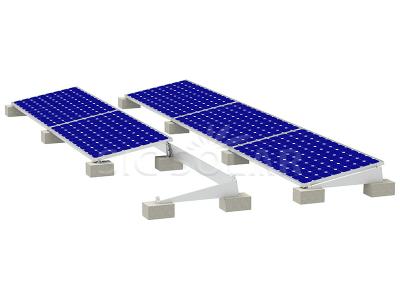
Roof type and covering profile determine which clamps and rails fit your project. Standing seam roofs use non-penetrating clamps sized to seam heights of 38, 50, or 76 mm. Trapezoidal sheet roofs have rib heights of 27–60 mm and require EPDM-gasketed screw penetration at the rib crown. Corrugated roofs need straddle blocks or brackets at purlin positions, with ridge-to-ridge widths of 76–152 mm.
Roof drawings matter just as much. You should document roof pitch, purlin section size, material grade, and span. Steep-slope roofs above 7° trigger ASCE 7-22 Section 29.4.4 wind coefficients. Parallel-to-slope mounting typically uses tilt angles of 5°–20°. Clamp spacing runs 600–1,500 mm on center, with perimeter and corner zones at 600–900 mm and interior zones at 1,200–1,500 mm. A screw pattern or stud finder confirms purlin locations. SIC SOLAR's mounting systems meet AS/NZS 1170 and JIS 8955:2011 for extreme weather, so your roof data feeds directly into compliant system design.

For ground-mounted projects, soil bearing capacity and topography determine foundation type and cost. Soft soils may require ground screws or helical piles, while rocky terrain often needs concrete foundations. A geotechnical report is essential. Terrain slope affects table elevations, post height, and earthwork. Cross-row slope is harder to accommodate than along-row variation because it changes effective tilt and shading geometry. Foundation costs run $0.018–$0.035 per watt including excavation, concrete, rebar, and anchor bolts. Concrete transport beyond 60 km significantly raises cost and may favor driven piles or ground screws. As an EPC contractor, you should share soil test reports covering soil type, bearing capacity, and prior foundation work before finalizing any solar mounting system project requirements.
Module dimensions and weight directly affect rail spacing, clamp size, and structural load calculations. You cannot finalize a solar mounting system quotation without the exact module datasheet. Commercial photovoltaic (“PV”) panels are generally larger and heavier than residential models, so generic assumptions will produce inaccurate pricing.
Collect the manufacturer datasheet for your selected module model before contacting any solar mounting system supplier. Record dimensions with and without the frame, module weight and tolerances, maximum mechanical load rating, clamp zones, mounting-hole locations, connector type, and cable lead length. Document operating temperature range, power rating, and warranty terms. Verify racking compatibility and account for mounting hardware that may extend beyond the array edge. Require a final approved layout and equipment schedule before ordering, since supply-chain substitutions can change footprint or weight.
|
Specification |
Typical Range |
|---|---|
|
Module length |
68–94 inches |
|
Module width |
44–51 inches |
|
Module weight |
47–85 pounds |
|
Largest available module |
|
Worked example using a 600W module (89.7 in × 44.6 in, 61 lbs) for a 100 kW target:
Modules needed: 100,000W ÷ 600W = 167 modules
Module-only area: 167 × (89.7 in × 44.6 in) ≈ 4,644 sq ft
Applying a 0.70 module-to-roof-area ratio: 4,644 ÷ 0.70 ≈ 6,634 sq ft of actual array footprint
Module weight alone: 167 × 61 lbs ≈ 10,187 lbs, before racking, wiring, or ballast
This demonstrates why module dimensions and weight are essential inputs for accurate mounting system quotes: they determine both the physical footprint and the structural load the mounting system must support.
Module quantity and orientation determine array layout and the bill of materials. A small commercial installation may need a simple structure, while a large solar farm can involve thousands of posts, rails, clamps, and fasteners. Portrait and landscape configurations require different rail arrangements and support positions. If you change the layout after structural design is complete, additional engineering or component changes become necessary. Provide accurate module dimensions and quantities so your supplier calculates material requirements precisely instead of quoting from assumptions.
|
Attribute |
Double Portrait / 2P |
Landscape Alternatives |
|---|---|---|
|
Slope direction |
Two module lengths form the slope direction |
Module width or multiple landscape modules form the slope direction |
|
Clamp zones |
Often uses long-side clamp zones |
Rail direction and clamp positions may differ |
|
Table height |
May create a taller high edge at the same tilt and clearance |
Can produce a different table height and row pitch |
|
Structural checks |
Member spans, wind effects and access must be checked for the exact module |
Compatibility must still follow the module manufacturer's mounting instructions |
|
Overall impact |
Neither layout is always better — compare energy yield, land use, steel quantity, foundation count, electrical routing, installation time and lifetime maintenance |
Same comparison applies |
Key layout inputs include slope length, table length, tilt angle, lower-edge clearance, upper-edge height, row pitch, support spacing, and module compatibility. The module manufacturer defines allowable clamp zones, minimum clamp length, bolt torque, and mechanical load ratings. These values must coordinate with the 2P rail arrangement. SIC SOLAR's R&D team continuously innovates to simplify installation and reduce labor costs, supporting commercial solar system design across global markets.
Mounting type and tilt angle shape your quote more than almost any other design choice. You must decide early whether your solar energy system will use roof-mount, ground-mount, carport, or tracker hardware. Each option carries different material costs, labor requirements, and foundation needs. Your supplier cannot price the job accurately without this information.
The available mounting options fall into five broad categories. Rooftop installation remains the most popular approach. Installers mount these systems on flat membrane, metal panel, and standing seam metal roofs. Fixed or ballasted ground mounts work well when you have open ground area. A low-profile ballasted option also exists for sites with limited penetration allowance. One or two-axis solar trackers make sense when maximizing power production is your priority. Hybrid solutions combine roof and ground-mounted systems to boost energy output for larger facilities. Carports turn parking lots into solar generators and provide covered parking with dual-purpose functionality.
Cost differences between roof and ground mounts are substantial. The table below shows typical installed cost ranges for a residential-scale project.
|
Cost Component |
Roof Mount |
Ground Mount |
Difference |
|---|---|---|---|
|
Panels + Inverter |
$10,000-$12,000 |
$10,000-$12,000 |
$0 (same equipment) |
|
Racking/Mounting |
$2,000-$3,000 |
$4,000-$6,000 |
+$2,000-$3,000 |
|
Foundation/Footings |
N/A (uses roof) |
$1,500-$3,500 |
+$1,500-$3,500 |
|
Trenching + Conduit |
N/A |
$1,500-$3,000 |
+$1,500-$3,000 |
|
Labor |
$3,000-$4,500 |
$4,000-$6,000 |
+$1,000-$1,500 |
|
Total Installed |
$22,000-$28,000 |
$26,000-$34,000 |
+$4,000-$6,000 |
|
Cost per Watt |
$2.20-$2.80 |
$2.60-$3.40 |
+$0.40-$0.60 |
Tilt angle drives energy production and structural loading. Ground mounts can be set to the optimal fixed tilt of 25-30 degrees facing true south for the Hudson Valley latitude (41-42°N). This orientation maximizes energy production. Roof mounts are constrained to the existing roof pitch. Typical pitches include 6/12 (~26.5°), 4/12 (18°), or 8/12 (33°). Each deviation from ideal reduces output. The production difference between a perfectly oriented ground mount and an average roof mount is 10-25% annually (1,200-3,000 kWh, or $180-$540/year at $0.15/kWh). Single-axis trackers boost output another 15-25% over fixed ground mounts. However, they add $3,000-$5,000 to system cost and require maintenance for moving parts.
Panels tilted at 30+ degrees shed snow faster than lower-angle installations. Ground mounts set to 30 degrees clear themselves after most light snowfalls. Roof mounts on a 4/12 pitch (18 degrees) hold snow longer and produce less winter energy as a result.
Your choice between fixed-tilt and adjustable tilt also affects the quote. Fixed-tilt systems cost less and require no seasonal adjustment. Adjustable-tilt systems capture more energy across seasons but add hardware and labor. Ballasted roof mounts avoid penetration and preserve roof warranties. Penetrated roof mounts cost less but require flashing and sealant work. Share your preference with your solar mounting system supplier before they finalize pricing.
Installation details determine labor scope and foundation cost. A typical ground-mount installation follows a defined sequence. First, site work covers clearing, grading, and erosion control. Second, a foundation contractor installs driven piles, helical piers, or concrete work. Third, the racking and structural steel assembly begins. Fourth, trenching creates conduit runs from the array to the electrical equipment. Fifth, crews install the panels. Sixth, electrical work mirrors the rooftop scope but with longer conduit runs.
Foundation design depends on your project site conditions. Your supplier can provide complimentary foundation recommendations for concrete embedment with the mount's calculation packet. You can use these recommendations to obtain cement estimates. Cement requirements depend on the foundation's depth and shape, and whether the mount uses a multi-pole design. Design and location data entered into the Solar Mount AutoDesigner determine foundation dimensions and shape.
Grounding and bonding components matter for code compliance and system safety. All parts needed to bond the array in preparation for equipment grounding are typically provided. Module clamps improve bonding by penetrating the PV module's coating while connecting it to the rail. One grounding lug is included for each column. These parts bond the mount's rails to the ground conductor. An electrician is needed to complete the grounding process. Depending on qualifications, you may need to contract a professional for wiring and grounding services.
Wire management and add-ons affect installation efficiency. Wire management clips are optional but helpful add-ons that keep the wiring process tidy. One micro-inverter adapter is needed for every inverter, optimizer, or automatic shutdown device incorporated into the mount's rails as part of equipment bonding and grounding. Other optional add-ons include tilt angle indicators for confirming and adjusting the mount's angle. All product add-ons can be purchased through the Project Portal.
Compatibility with existing structures requires careful review. For rooftop projects, you must confirm that the roof structure can handle the added load from mounting racks, panels, and ballast. For ground projects, you must verify that the soil can support the foundation type. Your EPC team should also check utility interconnection requirements early. These requirements can affect system design and equipment selection. A mismatch between your mounting hardware and existing structures leads to costly redesigns.
SIC SOLAR offers simple, durable, and economical mounting systems with a 10-year warranty and 25-year lifetime. The company's R&D team continuously innovates to simplify installation and reduce labor costs. Whether your solar system design calls for roof-mount, ground-mount, carport, or tracker hardware, SIC SOLAR can match the right solution to your solar mounting system project requirements. Their engineering support helps you finalize system design details before production begins.
Certifications and compliance documents often determine whether your project wins approval. You should prepare these items before requesting a solar mounting system quotation.
Different markets require different certifications. ISO9001 serves as the international quality management benchmark. CE and TUV indicate compliance for the European market, while EN 1990:2002 covers European structural design. ANSI applies to the United States. AS/NZS 1170 governs Australia and New Zealand, and JIS 8955:2011 applies to Japan. Your authority having jurisdiction will also require specific compliance documents for permit issuance.
|
Certification / Standard |
Market or Region Indicated |
|---|---|
|
ISO9001 |
International quality management benchmark |
|
CE |
European market |
|
TUV |
European market |
|
EN 1990:2002 |
European structural design standard |
|
ANSI |
United States |
|
AS/NZS 1170 |
Australia / New Zealand |
|
JIS 8955:2011 |
Japan |
A typical submittal includes the PE-stamped Structural Calculation Report (detailing ASCE 7 wind, snow, and seismic loads), detailed structural Shop Drawings, the manufacturer's UL 2703 Certificate and approved module matrix, and the official system Installation Manual. UL 2703 certification is required by the National Electrical Code for grounding path safety and fire resistance. Authorities will reject permit applications using unlisted racking components. PE stamping is mandatory for commercial, industrial, and utility-scale projects. All 50 states adopt NEC and IBC variations, making listed and labeled equipment universally required for permit issuance.
Delivery terms affect your quoted price and lead time. FOB, CIF, and DDP each shift cost and risk between you and your solar mounting system supplier. Packaging requirements matter for container loading efficiency and site handling. Pallet labeling helps your crew identify parts quickly during installation. Share your site delivery windows early so production slots align with your construction schedule.
Your EPC team should also confirm utility interconnection deadlines. These dates can pressure your procurement window and require expedited production. SIC SOLAR ensures strict quality control at every stage and serves global markets with reliable delivery. The company's 10-year warranty and 25-year lifetime guarantee long-term performance for your solar mounting system project requirements.
Complete information across all five categories determines how fast and accurate your solar mounting system quotation will be. A standardized information package reduces procurement risk and strengthens your relationship with every solar mounting system supplier. Use these categories as a pre-quote checklist for each request. Centralize site data, confirm buildable areas, and verify grid feasibility early. SIC SOLAR designs solutions tailored to local conditions while applying international best practice. Thorough preparation accelerates delivery and avoids costly redesigns. Treat what information should EPC contractors provide as your standard intake process, and your solar energy system will move from quote to construction with fewer surprises. Your EPC team saves time, money, and rework.
Location, capacity, roof or ground data, module specs, and commercial terms drive speed. A complete package lets your solar mounting system supplier price the job without follow-up questions. Missing items force revisions and delay your schedule.
Check certifications, warranty terms, and global project experience. SIC SOLAR holds ISO9001, meets AS/NZS 1170 and JIS 8955:2011, and backs systems with a 10-year warranty and 25-year lifetime. Ask for references in your region.
Confirm them early, before finalizing your solar mounting system project requirements. Interconnection deadlines can pressure your procurement window and force expedited production. Share these dates with your supplier so production slots align with your construction schedule.
State whether you plan portrait or landscape layout. Orientation changes rail direction, clamp positions, and table height. Provide the module datasheet so your supplier calculates material needs precisely instead of quoting from assumptions.
You can, but expect conditional pricing. Roof pitch, purlin spacing, and covering profile determine clamp and rail selection. Send drawings as soon as possible so your EPC team avoids costly redesigns later.



 IPv6 network supported
 English
 Deutsch
 español
 português
 Nederlands
 العربية
 日本語
 한국의
 Melayu
 Tiếng việt